
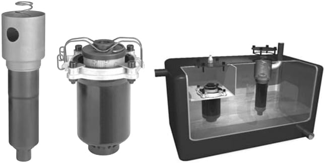
RFM…S, RFM…Set, and Typical Installation of Both Models
RFM…S and RFM…Set Series
Inside Tank Return Line Filters
145 PSI • Up to 132 GPM
Features:
- Unique design allows filter to be installed completely inside of the reservoir tank. This saves space, protects the filter, reduces leak points and reduces overall installation cost.
- Lightweight unit requiring no filter head reduces pressure drop while decreasing cost.
- Excellent option for low overhead clearance applications.
- Allows pre-filtration of new make-up oil assuring cleanliness of system.
- Contamination Basket prevents filtered contamination from re-entering the tank during element changeout on 330 and 500 size models.
- Simplifies element change-out procedure in the field.
- RFM Set configuration (tank plenum) allows for multiple returns to enter plenum without manifolding.
Installation
RFM…SET: Inside Tank Filters are installed into a separate chamber built into the reservoir tank via the filter ring and 4 bolts. More than one filter may be installed in the chamber if required for capacity. This procedure will require a hole to be cut into the top of the reservoir tank and an access cover fastened to the tank for each filter installed. The inlet piping for return should be connected through the tank wall into the separate chamber. A clip installed on the filter ring holds the element in place during filtration operations, and facilitates easy removal for element change out.
RFM…S: Inside Tank Filters are installed to the top of the tank by welding the inner chamber to the tank cover. This procedure will require a hole to be cut into the top of the reservoir tank and an access cover fastened to the tank. A smaller hole must be cut somewhere in the tank for the return line piping to pass through. The hole located in the side of the inner chamber must be directed towards the return line piping. The inlet piping for return should then be welded through the tank wall and to the inner chamber. The spring located between the element and the access cover provides force to hold element in place during filter operation. Multiple filters can be installed in the tank.
Technical Details
| Port Connection (Outlet) | 75/165/185: 1.26˝ Smooth Port 330/500: 2˝ NPT |
| Flow Direction | Inlet: Side Outlet: Bottom |
| Construction Materials | Chamber: Steel (75/165/185) Bowl: Plastic Ring: Aluminum (330/500) |
| Flow Capacity | 75: 20 gpm (75 lpm) 165: 43 gpm (165 lpm) 185: 49 gpm (185 lpm) 330: 87 gpm (330 lpm) 500: 132 gpm (500 lpm) |
| Housing Pressure Rating | Max. Operating Pressure: 145 psi (10 bar) Proof Pressure: 218 psi (15 bar) Fatigue Pressure: 145 psi (10 bar) Burst Pressure: >580 psi (40 bar) |
| Element Collapse Pressure Rating | BN/HC, W/HC 250 psid (17 bar) ECO/N, BN/AM, P/HC, AM 145 psid (10 bar) |
| Fluid Temperature Range | -22° to 250°F (-30° to 121°C) |
| Fluid Compatibility | Compatible with all petroleum oils and synthetic fluids rated for use with Fluoro-Rubber or Ethylene Propylene seals. Contact HYDAC for information on special housing and element constructions available for use with water glycols, oil/water emulsions, and HWBF. |
| Bypass Valve Cracking Pressure | ΔP = 43 psid (3 bar) + 10% ΔP = 87 psid (6 bar) + 10% |