Data Sheet 64: Computing Power to a Hydraulic System
Finding the Load Resistance
Design of the circuit itself has been covered in other Data Sheet issues and in the series of Womack “Industrial Fluid Power” textbooks. In this issue we will deal with cylinder systems and assume the circuit diagram has already been designed. Our aim will be to calculate the input power and pressure to move a certain load resistance at a certain rate of speed. Then to arrive at optimum pressure and flow levels to satisfy the load conditions so the best combination of cylinder and pump can be selected.
But before any HP calculations can be made, The amount of force to move the load must be determined as accurately as possible. Speed, of course, is not as demanding a requirement, and a speed variation either slower or faster is usually acceptable in order to precisely match the HP requirement of the system to the power output of the prime mover.
For example, if a 30-ton press is being designed, the load specifications will be straightforward: the cylinder(s) must produce 60,000 lbs. of force and must cycle (so many) times a minute. From these data we can easily calculate the estimated HP input, and can select a cylinder and pump combination to best meet the load requirement.
But on some applications the specifications are not so clear. Perhaps the hydraulic machine must perform a certain operation on a designated workpiece at a certain rate of speed, and the amount of force to perform this operation is not precisely known. On these applications the designer must make whatever calculations can be made, perhaps involving load weight (or mass), frictional resistance, hardness or strength of the material being worked, etc. The application can sometimes be compared with a similar application on which the force is known. At any rate, no further HP calculations can be made until the load resistance is determined. Before going into production to make several of these machines, a prototype machine is built to prove (or disprove) the accuracy of the load resistance estimate.

Computing Output Horsepower
Before making power loss calculations, the output of the machine must be specified in HP from the cylinder. If specified in terms of force and speed, convert to HP with the standard mechanical HP formula in which 1 HP = 33,000 ft-lbs per minute:
HP = [F × D × 60] ÷ [T × 12 × 33,000], in which:
F is cylinder force, in lbs.
D is cylinder stroke, inches.
T is time for cylinder stroke, in seconds.
60 and 12 convert minutes to seconds and feet to inches.

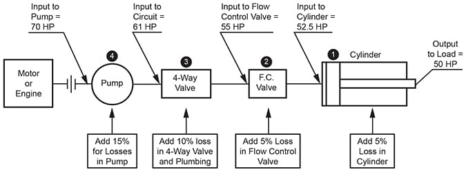
Figure 1. Block diagram of a typical hydraulic cylinder system operating with 50 HP output.
Estimating HP Input to the System
Figure 1 shows a typical 50 HP hydraulic system with the major areas of power loss between prime mover and cylinder illustrated. In order to determine the required HP from the prime mover to deliver 50 HP out, it is necessary to start with the mechanical power delivered to the load by the cylinder, then to work backward, one step at a time, until reaching the prime mover output shaft.
Item 1, Cylinder. The friction loss in most hydraulic cylinders should not exceed 5%, and at pressures above 1,500 PSI the loss may be less than 5%.
In Figure 1, assuming cylinder loss to be 5%, the fluid power input to the cylinder must be:
HP = 50 ÷ 0.95 = 52.6
Item 2, Row Control Valve. When using a series connected flow control valve or if metering speed in a mobile system by modulating the 4-way valve spool, the pump must supply maximum power to the system regardless of the cylinder speed, as long as the system is in motion. Any power not transferred to the load is converted into heat by oil discharge across the system relief valve. Operating loss for pressure compensated flow control valves will be about 3 to 5% on pressures above 1,500 PSI, and will be about 6 to 10% if the operating pressure is below 1,500 PSI.
In Figure 1, the fluid-power input to the flow control valve, assuming 5% loss, must be:
HP = 52.6 ÷ 0.95 = 55.4
Item 3, 4-Way Valve and Plumbing. The fluid power delivered by the pump into the circuit must include 50 HP for the load plus all system losses downstream of the pump.
In a conservatively designed industrial fluid power system operating at pressures above 1,500 PSI, flow losses through 4-way valve and plumbing may amount to only 5%. At operating pressures less than 1,500 PSI these losses may amount to 10%. Most mobile systems are intentionally designed with higher circuit losses in order to economize on construction by using smaller valving and plumbing, and circuit losses may amount to 20% of the input power.
In Figure 1, assuming 10% circuit losses, the fluid power required from the pump must be:
HP = 55.4 ÷ 0.90 = 61.5
Item 4, Pump. The mechanical power input to the pump shaft must include 50 HP for the load plus extra power to supply all losses downstream, plus loss in the pump itself. The loss through most gear pumps and variable displacement vane pumps will vary from 15 to 30%, with 20% being about average. The loss through balanced vane pumps will be about 15%, and the loss through a high quality piston pump may be as low as 10%.
In Figure 1, assuming a 15% loss in the pump, the power input to the pump shaft must be:
HP = 61.5 ÷ 0.85 = 72.4
This is the output rating of an electric motor or engine acting as prime mover for the system.
Sizing the Cylinder
There are several piston sizes which would produce the force needed by the load. The designer must tentatively select a suitable PSI level. This selection may depend on the brand, type, or model pump which he expects to use. After deciding on a pressure level, a cylinder size can be selected with a piston area large enough to produce the load force at the selected pressure. The cylinder need not be oversized except for 5% to take care of cylinder losses.
Sizing the Pump
The pump must operate at a pressure to supply force for the load plus pressure for flow and friction losses from pump outlet to cylinder output. Pump to load pressure ratio is the same as power ratio between the same points. Pump output to cylinder output ratio is: 61.5 ÷ 50 = 1.23. Therefore, pump pressure must be 1.23 times load pressure. Suppose in Figure 1, for example, 2,000 PSI is theoretical pressure calculated for the load. The pump must operate at 1.23 × 2,000 = 2,460 PSI. The pump relief valve must be set so its cracking pressure is at least 2,460 PSI or higher.
After the cylinder bore and pump pressure have been established, the pump flow rate, in gallons per minute (GPM) to cause the cylinder to move at the specified speed must be calculated using the standard formula:
GPM = S × A ÷ 231, in which:
S is the required speed, inches per minute
A is piston area, square inches
No extra allowance need be made for loss of flow through the system because no oil will be lost from the system regardless of power and pressure losses.
Select a pump which is capable of operating at 2,460 PSI and which produces no more flow than actually required for the specified cylinder speed. Oversizing the pump for flow and forcing a part of the flow across a relief valve by the speed control valve will add to the system HP input requirements as well as creating unwanted heat in the oil. Please refer to these other design data sheet issues for additional information affecting the selection of components.
Design Data Sheets 1 and 46 for heat exchanger information.
Design Data Sheet 4 for acceleration of a massive load.
Design Data Sheet 29 for life expectancy of a piston pump.
Design Data Sheets 56 and 57 for recommended plumbing sizes.
Multiple Branch Systems
Obviously, if two or more branch circuits operate at the same time from a common pump, the input HP will have to be sufficient to take care of the maximum load. Calculate each branch separately and add them together.
Pressure Reducing Valves. If a reducing valve is placed to reduce pressure in one branch, the power lost in the reducing valve will add to the HP load on the prime mover. Calculate power lost (while that branch is operating):
HP (power loss) = PSI × GPM ÷ 1,714, in which:
PSI is pressure difference across the reducing valve.
GPM is rate of oil flow through the reducing valve.
Spool-Type Row Dividers. If the divider has a 1:1 flow split, calculate input HP to the branch operating at the higher pressure, then double this figure. Even though the other branch is producing less power on its cylinder, the difference in power between the two branches is consumed as heat generated in the flow divider.
© 1990 by Womack Machine Supply Co. This company assumes no liability for errors in data nor in safe and/or satisfactory operation of equipment designed from this information.