Data Sheet 46: Tips on Selection of Shell and Tube Heat Exchangers
The reader may want to refer to Design Data Sheet #1 for formula relating to heat transfer and for additional information on heat exchanger selection.
Information in this issue relates only to industrial hydraulic systems using mineral base oil and using water as a cooling medium. The task of selecting an appropriate size heat exchanger for this type of application is quite easy after a few basic facts on heat and heat transfer are learned.
Catalog selection data published by manufacturers of heat exchangers would lead a person to believe it is a highly complicated problem involving precise mathematical calculations. This is true, of course, when calculating the exact rating of heat exchanger models for catalog purposes. But from a practical standpoint these precise calculations are of little value because rarely is it possible to arrive at an exact amount of heat which must be removed from the hydraulic system. Therefore, if the data used in the mathematical equations are incorrect, the equations will not produce an accurate answer.
Any fluid power designer, by using a fair amount of common sense, can come up with a better selection than can a computer if that computer is fed with incorrect information. Here are a few facts about heat transfer:
Measurement of Heat Load. In hydraulic systems it is usually more convenient to express heat losses and heat transfer in HP rather than BTU/minute because other system calculations involving power are expressed in HP. Design Data Sheet #1 gives conversions into HP from kilowatts, BTU, etc.
Levelling-Off Temperature. In any hydraulic system, when the system is first started, temperature of oil in the reservoir will gradually rise from room temperature (ambient) to a “levelling-off” temperature in a period of time which may vary from 15 minutes to several hours, depending on the type of system, the duty cycle, and its natural heat radiation capability. After this, no matter how long the system remains in operation, the oil temperature will rise no higher unless there should be a change either in the duty cycle or in the ambient temperature. At this temperature a balance has been reached between the rate at which heat is generated and the rate at which the system can dispose of it by natural radiation cooling. If this levelling-off temperature is low enough to be acceptable, no heat exchanger is needed. The purpose of a heat exchanger is simply to reduce the leveling off temperature to an acceptable level. Design Data Sheet #1 gives information on a procedure for finding heat exchanger capacity to supplement an existing system.

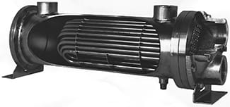
Shell and Tube Heat Exchanger. Consists of a bundle
of brass or naval bronze tubes inside an outer shell,
and enclosed by a pair of end caps. Cooling water is
circulated through the tubes; hot oil is circulated inside
the shell and around the outside of the tubes.
 |
Natural Radiation Cooling. Heat is radiated from all metal parts of a hydraulic system including oil reservoir, cylinder, hydraulic motor, valves, and from iron and steel fittings and plumbing. On many low power systems the natural radiation is adequate to keep the levelling-off temperature to an acceptable level, especially where the duty cycle is short. But on larger systems the area of the heat radiating surfaces is far less in proportion to the system power. On systems larger than 25 HP, and with long duty cycle, a heat exchanger is usually necessary to avoid a high levelling-off temperature.
Estimating Heat Load. Before any heat exchanger can be intelligently selected, an estimate must be made of the probable system losses. Most of these losses will turn up as heat, which must be disposed of by a heat exchanger with the help of natural radiation. It is seldom that these losses can be calculated accurately. Therefore, the designer has to rely a lot on common sense, and should select a heat exchanger which he is sure will have more than sufficient capacity. An oversize heat exchanger, while its first cost is higher, will not consume any more cooling water than a smaller unit. The water control valve will always meter in only enough water to match the heat load whatever the size of the heat exchanger. A “common sense” method of estimating the system heat load is described next:
Maximum Heat Exchanger Capacity. Common sense tells us that the heat exchanger capacity will never have to be greater than the HP input even if the entire input was going into heat. In all except very unusual systems, the power losses (heat to be removed) will be less than 50% of the input power and usually will be more like 25%. This is a very rough way of estimating heat load. Sometimes the heat load can be more accurately estimated as follows:
Heat Generation in the System. Each hydraulic pump or motor can be expected to waste about 15% of its input power through internal slippage, and most of this ends up as heat in the oil. Additional heat comes from flow of oil across relief valves, flow control valves, and pressure reducing valves. This is calculated with the fluid power formula:
HP = GPM × PSI ÷ 1,714
In a properly plumbed system it has been estimated that about 10% to 15% of the input power will go into heat from flow losses through plumbing, fittings, and directional control valves. If all of these losses are calculated and averaged over a period of about an hour, a heat exchanger having this capacity will be more than sufficient.
Cooling Water. Our rule-of-thumb (see box on front Of this sheet) requires an available flow of water of 1/2 the oil flow rate. When using the modulating type water control described in the next paragraph, the water will not be flowing continuously at this rate. During start-up and probably for several hours, no water at all may flow. Then, the actual flow rate thereafter will be only that amount needed to carry away the heat, to maintain the levelling-off temperature set on the water control. Thus the actual flow, averaged over a day’s operation may be only a small fraction of the volume provided for maximum heat removal conditions.

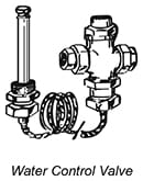
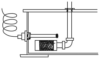
Water Control Valve. A modulating type water control valve should be installed upstream of the heat exchanger. This valve has a temperature sensing bulb connected by a 6-foot long capillary tube into the main valve. The bulb must be immersed in the hydraulic oil. Usually the reservoir is the most convenient location for immersion, although any part of the system may be used for temperature sensing. The control is then adjusted for the desired leveling-off temperature. Water remains completely cut off until system temperature approaches the setting of the control valve. The valve then modulates the water flow, allowing only enough flow to keep oil temperature from rising any further.
We do not recommend a 2-way solenoid water valve controlled by a temperature switch, as this method tends to waste water.

The bulb of the water control valve must be
immersed in the hydraulic oil.
Volume of Oil Flow. An oil flow rate near the mid range of the heat exchanger flow rating gives optimum performance. At higher oil flows more heat will be transferred but there will be much higher flow losses through the heat exchanger and more back pressure on the system. At lower flows the heat removal capacity is reduced.
How to Apply the Rule-of-Thumb
The rule of thumb in the box on the front side of this sheet is based on an available volume of cooling water of 1/2 GPM or more of water for each 1 GPM of oil flow, and at a temperature no higher than 90°F. Reservoir temperature will be held below 150°F provided the ambient (room) temperature does not exceed 100°F.
- You should first estimate, as realistically as you can, the amount of HP in heat which will have to be disposed of through the heat exchanger. Use the information in the opposite column and on the front side of this sheet as a guide.
- You must know the volume of oil, in GPM, which will flow through the heat exchanger when installed in the circuit position you have chosen.
- The heat exchanger catalog from which you are making a selection must show the square foot transfer area of each model, and must show the minimum and maximum flow limits, on the oil side, for each model.
- Select a model for which your GPM oil flow falls in the 1/3rd to 2/3rds range between the minimum and maximum mum flow limits given for that model.
- Use the rule-of-thumb to see if the chosen model will transfer the amount of heat which you have estimated for your system. If it will not, select the next larger model.
More information will be presented in future issues on selection of air cooled heat exchangers, and on installation and maintenance of all heat exchangers.
© 1990 by Womack Machine Supply Co. This company assumes no liability for errors in data nor in safe and/or satisfactory operation of equipment designed from this information.