Data Sheet 31: A Study of Rotary-Type Flow Dividers
A flow divider accepts a flow of oil under pressure, usually from a hydraulic pump, and divides it into two streams of equal (or unequal) flow volume for operation of two independent branch circuits from one pump, or for synchronization of two identical cylinders. Spool-type flow dividers were described in Design Data Sheet 26. This issue covers rotary type flow dividers. These operate quite differently, and require different circuit techniques.
A rotary flow divider is like two gear-type pumps or motors with shafts joined, except that the two sections are built in one housing and use a common shaft. Being mechanically joined, they are forced to rotate at the same speed, and to meter equal flows to their outlet ports.
Most rotary flow dividers are limited to two sections of equal displacement, and this discussion will be limited to this type. When a greater number of sections, or unequal displacement between sections is used, problems of extreme pressure intensification may develop.
Rotary dividers are more efficient than spool-type dividers because the assigned power of an unused outlet port can be transferred mechanically to the other section instead of being converted into heat as is the case with spool-type dividers. Not only does this reduce heat in the oil, it conserves input power to the system, it permits the pump to operate at a lower average pressure, and makes possible the efficient operation of a system with unequally loaded branch circuits (an advantage over spool-type dividers).
Rotary dividers are probably most efficient when the combined displacement of both sections is approximately equal to pump displacement. They are definitely limited to proportional dividing; priority dividing (as in a power steering system) is not possible with them.
Directional Valves
A rotary flow divider has a unique ability to transmit torque from one section to the other through their common shaft. To take advantage of this, the 4-way valve must have open flow to tank when in center position. A tandem or open center spool should be used; a valve with closed pressure port in neutral would cause the unused power to be converted into heat across a relief valve instead of being transferred through the flow divider and used in the other section.
Relief Valves
Even though relief valves may be used elsewhere in the system, it is important to place a relief valve on each outlet port of the flow divider, and to set each valve to the maximum pressure required in that branch.
A relief valve directly on the pump – pressure line is optional, and may not be necessary. If desired, one may be used as an extra safeguard, to back up the ones on the flow divider outlets, in the event the flow divider should lock up. A pump relief valve, by itself, would not give complete protection because of the pressure intensification which may develop (see opposite side of this sheet). If used, it should be adjusted to the same pressure as the relief valve on the side of the flow divider which is most heavily loaded.
Working Circuit
Figure 1 shows a 2-branch circuit with a different load on each branch cylinder. Both 4-way valves are in neutral. Gauge readings on the cylinders are taken as the pressure which is required to move each load.
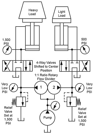
Figure 1. Basic circuit for operating two branch circuits
from one pump. Branch circuits are carrying different loads.
The reaction of pump pressure to branch circuit pressure,
when the branches are working, is shown in Figures 2 and 3.
Figures 2 and 3 on this sheet show pump pressure required when both branches are working and when only one branch is working.
Diagrams are in block form to illustrate flow divider action. They are not complete working circuits. A pressure relief valve (not shown) should be connected across each outlet of the flow divider. All 4-way valves should have tandem center spools.
Operation of Two Independent Branches
Figure 2. Block diagram of Figure 1. Two branch circuits, carrying unequal loads, are to be operated from one pump. Notice the pressure level at which the pump operates in relation to the pressure appearing in each branch.
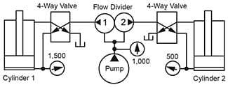
Figure 2. Block diagram of the circuit of Figure 1.
Both branch circuits are working. Compare the pump
pressure with that on each of the two cylinder ports.
Cylinder 2 requires 500 PSI for its load. This pressure is supplied entirely by the pump through Section 2 of the flow divider.
Cylinder 1 requires 1,500 PSI for its load. A part of this pressure, approximately half of it, is furnished directly by the pump working through Section 1 of the flow divider. The remainder is furnished by torque developed in Section 2 as that section acts like a hydraulic motor, furnishing power to drive Section 1 which is acting like a hydraulic pump. In other words, any excess of power not needed in the branch with lighter load (Section 2 in this case), is transferred mechanically to Section 1 and is used there instead of being dissipated in heat as in a spool-type divider. If the flow divider has a 1:1 ratio, the pump should be working at a pressure which splits the difference between pressure requirements in the two branches.
Figure 3. This is also a block diagram of the circuit of Figure 1, but with one branch working and the other branch stopped. The 4-way valve to Cylinder 1 is shifted to a working position and Cylinder 1 is extending. The 4-way valve to Cylinder 2 is in neutral, and this part of the pump oil can flow to tank. Remember, these 4-way valves should be tandem center type to allow free oil flow to tank without passing across a relief valve when the 4-way valve is centered.
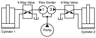
Figure 3. Block diagram of the circuit of Figure 1.
Cylinder on the right is stopped and its share of the
power is transferred to the working cylinder on the left.
Half of the 1,500 PSI needed by Cylinder 1 is supplied directly from the pump through Section 1 of the divider. The other 750 PSI is furnished by power transfer through the divider from Section 2, where it ) is not needed, to section 1. If the divider has a 1:1 ratio, the pump only has to put up half the pressure needed if one side is not working and if that unused section of the divider is vented to tank.
Synchronizing Two Cylinders
Another type of application for rotary-type flow dividers is to keep two cylinders (attached to the same mechanism) in step, moving at the same rate of speed. The cylinders should be identical in bore and stroke, and the flow divider should have a 1:1 ratio. The 4-way valves may have any type of spool center.
One limitation of a rotary divider is that it cannot be used in reverse as a flow combiner. One section, connected to the lagging cylinder, would cavitate. Two possible circuit arrangements for keeping two cylinders in step are shown in Figures 4 and 5.
Figure 4. A 2-section divider may be used in the pump line. The two outlets than feed a pair of identical 4-way valves, usually solenoid type, which are always energized and de-energized at the same time.
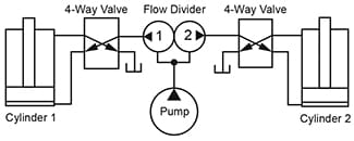
Figure 4. Block diagram of synchronizing circuit
for two cylinders using one flow divider and two
4-way valves which must be shifted simultaneously.
Figure 5. Where only one 4-way valve is to be used, and where synchronization is to be in both directions of travel, two flow dividers are required, one for each direction of travel. Four relief valves are required, one connected to each outlet port of each flow divider.
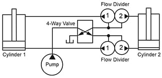
Figure 5. Block diagram of synchronizing circuit
for two cylinders using one 4-way valve and two flow
dividers, one for each direction of cylinder travel.
© 1990 by Womack Machine Supply Co. This company assumes no liability for errors in data nor in safe and/or satisfactory operation of equipment designed from this information.