Data Sheet 26: Spool-Type Proportional Flow Dividers
Flow dividers – are devices which split the flow from a pump into two streams for independently operating two branch circuits. Advantages of flow divider operation are:
- Only one pump is required. This is a particular advantage in the saving of space, and reducing cost.
- Each branch circuit is isolated from the other: changing loads on one branch will not affect the pressure or flow in the other branch. Flow dividers are only for hydraulic systems; they are not applicable to most industrial air systems.
Two general methods are used for dividing a flow of oil. One method uses a sliding spool; the other method uses rotary construction, and operates similarly to two gear-type pumps with shafts coupled together. The two gear sections meter proportional amounts of oil to each outlet.
The action of spool-type and rotary-type dividers is quite different, and each requires a degree of technical knowledge to apply them properly and on suitable applications.
Spool-type dividers can be built to deliver proportional flows from two outlets, or to deliver a priority flow from one outlet with excess flow coming out the other outlet. Only the spool-type, proportional divider will be described in this issue; the other types will be the subject of a later issue.
Spool-type proportional dividers usually have equal division to the two outlets (1:1 ratio). They are practical with ratios as high as 4:1. Beyond this, the accuracy is poor.
The two most common types of applications are shown in the diagrams, Figures 1 and 2.

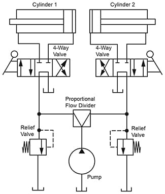
Figure 1. Divider splits pump flow equally or unequally
for independent operation of two cylinders which
may be the same or different bore and stroke.
Figure 1. Two Independent Circuits. Each branch circuit receives its proportional share of the pump oil. It is most important to have a relief valve on each branch to protect the pump if the cylinder in one branch should be overloaded or should stall. This would not only overload the pump, but would cause the other cylinder to stop because the flow divider spool would cut off its flow. Usually the two relief valves should be adjusted to the same pressure setting.
The 4-way valves may have any type of center position. Tandem center valves are shown, and the pump would be unloaded when both vales are centered. But remember, if only one cylinder is working, the other side of the flow divider cannot unload through the tandem center of its 4-way valve. The divider spool will move into a throttling position. Only when both 4-way valves are centered can the pump unload to a minimum pressure about 100 PSI (this minimum PSI is due to pressure drop through the divider).
Design Limitations of Figure 1. A flow divider instead of two separate pumps is recommended only on those systems where both cylinders will be working for approximately the same length of time during the same time intervals, a certain amount of heat will be generated in the oil, and this must be considered in the system design. If possible, select bore diameters of cylinders or displacements of hydraulic motors so both branch circuits will be able to work at about the same pressure. Remember that one outlet of a flow divider cannot be unloaded while the other outlet is working.

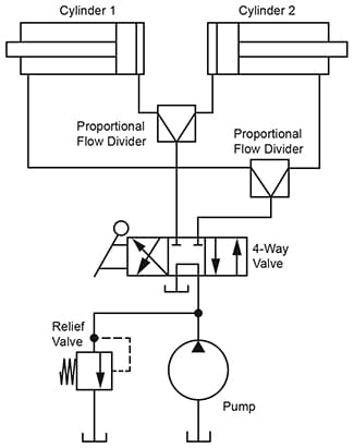
Figure 2. Flow dividers keep two unequally loaded
cylinders moving at the same rate of speed,
forward and reverse. Dividers split the flow equally
to two cylinders of identical bore and stroke.
Figure 2. For synchronizing the movement of two cylinders, the flow divider should have a 1:1 ratio, and the cylinders should have the same bore and stroke. Accuracy of flow division is usually about ± 5%, but may vary slightly according to volume of oil flow, degree of unbalance in load between the cylinders, and sometimes other factors.
To synchronize the cylinders in both directions of travel, two flow dividers must be used. Or, one unit may be used if it is designed to divide flow in one direction and combine equal flows in the reverse direction. A unit designed only for dividing will not combine equal flows; reverse flow is uncontrolled as it would be in passing through a pair of plain orifices. To reduce power losses in reverse flow, check valves may be placed around the divider.
Clamp and Work Application for a Proportional Flow Divider
In this unusual application, a flow divider valve is used instead of a sequence valve which normally would be used to program two hydraulic cylinders in a clamp and work application.

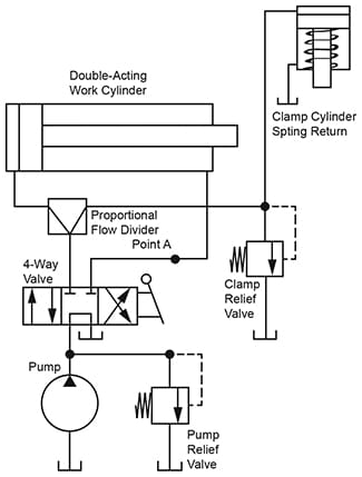
Figure 3. Unusual clamp and work circuit using a
flow divider instead of a sequence valve. The clamp
is isolated from the work cylinder by the flow divider.
In any clamp and work application, the clamp acts first, and when it has “bottomed out” against the workpiece, it must come up to near full clamping force before the work cylinder moves a cutting tool into the work. A problem in some circuits using a sequence valve is to limit the hydraulic pressure on the clamp to less than that on the work cylinder, usually to protect the workpiece from distortion or damage.
In this circuit, the clamp relief valve can be adjusted to any desired pressure equal to or less than the setting of the pump relief valve. Then, the work cylinder can operate at full pump relief pressure while the clamp cylinder can be limited to any desired lower pressure.
Both cylinders start to move when the 4-way valve is shifted to forward position, and the work cylinder must be located a sufficient distance from the workpiece so the cutting tool will not engage until the clamp cylinder has reached the workpiece and built up clamping force. Since the clamp cylinder is usually of small bore and short stroke, and the work cylinder much larger, the clamp should move to clamping position quickly, before the work cylinder can move very far.
At the option of the designer, the flow divider can have a 1:1 division ratio, or can have up to a 4:1 ratio, depending on the relative size of the two cylinders and the action desired. When the clamp stalls against the workpiece, its share of the oil goes across the clamp relief valve and generates heat during this period, and this fact must be considered in the design.
When the 4-way valve is shifted to retract the cylinders, all pump oil goes to the work cylinder, and the clamp retracts by spring force. If the clamp is double-acting, its rod port may be teed into Point A, causing it to retract by power. Return oil will pass in reverse through the divider as through an uncompensated orifice. If desired, a free return check valve can be connected on the left side of the flow divider.
On applications where the clamp must remain holding during retraction of the work cylinder, the circuit must be modified to retain the oil in the clamp until the work cylinder reaches home. Pressure build-up at Point A can be used to open a sequence valve or pilot open a dump valve to release the clamp.
© 1990 by Womack Machine Supply Co. This company assumes no liability for errors in data nor in safe and/or satisfactory operation of equipment designed from this information.