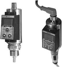
ETS 300 Series
The ETS 300 is a compact, electronic temperature switch with digital display. It is used with the TFP 100 temperature sensor, which was especially developed for tank mounting, or with its own integral sensor.
The ETS 300 has a 2 temperature ranges allowing for use in a wide range of industrial applications: -13° to 212°F (-25° to 100° C) and -22° to 302°F (-30° to 150°C).
The ETS 300 is offered with one or two switching outputs with an optional 4 to 20 mA analog output signal for remote temperature monitoring.
The switching points and hysteresis are easily adjustable via the membrane keypad. Other parameters are accessible and displayed on the digital readout, then adjustable via the keypad.
Technical Details
| INPUT DATA FOR INTEGRAL SENSOR | |
| Measuring range | -13° to 212°F (-25° to 100°C) |
| Pressure resistance | 13,000 psi (600 bar) |
| Hydraulic connection | G 1/2 A male |
| Torque rating | approx. 33 lb-ft (45 Nm) |
| Parts in contact with media | Stainless steel, Seal: FPM |
| INPUT DATA FOR SEPARATE SENSOR | |
| Display range | -22 to 302°F (-30° to 150°C) |
| Sensor connection | M 12×1, 4 pole |
| OUTPUT DATA | |
| Accuracy (display, analog output) | ≤ ± 2.0°F (≤ ± 1.0°C) |
| Temperature drift (zero point and range) | ≤ ± 0.0085% / °F |
| Reaction time (T09) | approx. 20 s |
| Analog output | 4 to 20 mA, ohmic resistance ≤ 400 |
| SWITCHING OUTPUTS | |
| Type | PNP transistor output |
| Switching current | max. 1.2 A |
| AMBIENT CONDITIONS | |
| Temperature range of medium | -13° to 212°F (integral sensor) |
| Ambient temperature range | -13° to 176°F (-25° to 80°C) |
| Storage temperature range | -40° to 176°F (-40° to 80°C) |
| Compensated temperature range | -14° to 158°F (-26° to 70°C) |
| CE mark | EN 61000-6-1, EN 61000-6-2, EN 61000-6-3, EN 61000-6-4 |
| Vibration resistance | approx. 10 g / 0 to 500 Hz |
| Shock resistance | approx. 50 g / 1ms |
| OTHER DATA | |
| Supply voltage | 20 to 32 VDC |
| Current consumption | approx. 100 mA (without switching output) |
| Safety type | IP 65 |
| Material of housing | tube: stainless steel keypad housing: PA6.6 Gf30 |
| Display | 3 digit, 7 segment LED, red, height of digits 9.2 mm |
| Weight | approx. 300 g |
| TEMPERATURE SENSOR TFP 100 | |
| Temperature range of medium | -40° to 257°F (-40° to 125°C) |
| Electrical connection | 4 pole plug M18x1 |
| SAFETY SLEEVE FOR TANK-MOUNTING THE TFP 100 | |
| Parts in contact with medium | All materials compatible with nickel |

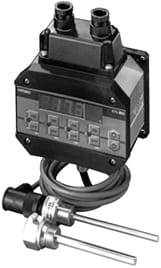
ETS 1700 Series
The electronic temperature switch ETS 1700 is used together with the temperature sensor TFP 100, which was specifically developed for tank mounting.
The 4 digit display can indicate either the actual temperature, one of the switching points, or the maximum temperature. The maximum temperature indicates the highest temperature which has occurred since the unit was switched on or last reset.
The 4 switching outputs can be used to control heating and cooling processes in hydraulic systems. All switching and switch-back points, which are independent of each other, can be adjusted very simply via a membrane keypad. For incorporation into monitoring systems (e.g. with PLC), an analog output (4 to 20 mA or 0 to 10 V) is also available.
Technical Details
| INPUT DATA | |
| Measuring range | 32° to 212°F (0° to 100°C) |
| OUTPUT DATA | |
| Output signal | 4 to 20 mA, ohmic resistance ≤ 400 0 to 10 V, ohmic resistance ≥ 2k |
| Accuracy (display, analog output) | ≤ ± 1.0% of the measuring range |
| Repeatability | ≤ ± 0.25% of the measuring range |
| Temperature drift in the zero point | ≤ ± 0.054%/°F (≤ ± 0.03%/°C) |
| Ambient temperature range | ≤ ± 0.054%/°F (≤ ± 0.03%/°C) |
| Switching output type | 4 relays with change-over contacts in 2 groups (common supply of each group connected) |
| Switching voltage | 0.1 to 250 VAC / VDC |
| Switching current | 0.009 to 2 A |
| Switching capacity | 400 VA, 50 W (for inductive load use varistors) |
| Life expectancy of contacts | ≥ 20 million (minimum load) ≥ 1 million (maximum load) |
| Reaction time (without switching delay) | approx. 20 ms |
| Switching point setting range | 1.5 to 100% FS |
| Setting range of hysteresis / switch-back points | 1 to 99% FS |
| AMBIENT CONDITIONS | |
| Ambient temperature range | -13 to 140 °F (-25 to 60°C) |
| Storage temperature range | -40 to 176 °F (-40 to 80°C) |
| CE mark | EN 61000-6-1, EN 61000-6-2, EN 61000-6-3, EN 61000-6-4 |
| Vibration resistance | approx. 5 g |
| Shock resistance | approx. 10 g |
| Sensor connection | 5 pole DIN connector |
| OTHER DATA | |
| Supply voltage | 22 to 32 VDC (residual ripple ≤ 10%) |
| Electrical connection | 14 pole terminal strip (cross-section of connection max. 1.5 mm²) |
| Current consumption | approx. 200 mA |
| Display | 4-digit, 7-segment LED, red, digits 13mm high |
| Safety type | IP 65 |
| Weight | approx. 800 g |

ETS 3000 Series
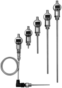
The electronic temperature switches ETS 3000 are available either as stand alone units with separate temperature probe or as pressure resistant types with integrated probe. Pressure resistant types have the sensor integrated and measuring ranges from -25° to 100°C. They stand pressures up to 600 bar which enable them to be mounted directly into pipes or manifolds. Types with separate temperature probes have measuring ranges from -30° to 150°C. As probes to be connected the HYDAC TFP 100 or other types of standard PT100 probes are applicable.
For evaluation and control the ETS 3000 feature 1 or 2 switching transistor outputs and, optionally, an analogue output. Maximum switching capacities are 1.2 A which enable connection of PLC input cards, as well as, direct connection of standard solenoid controlled valves. The digital displays are rotating over two axis (vertically and horizontally). Because of this, the ETS 3000 can be mounted in any position with their displays aligned into required positions. The 4 digit digital displays in standard operation show actual temperatures. Furthermore, maximum values or switch points can be displayed permanently. Selected by the user, either one of the measuring units °C or °F is displayed.
Technical Details
| INPUT PARAMETERS | INTEGRAL SENSOR PROBE | EXTERNAL SENSOR PROBE |
| Measurement range | -13° to 212°F (-25 to 100°C) | -22 to 302°F (-30 to 150°C) |
| Pressure resistance | 600 bar (18 mm) 50 bar (100, 250, 350 mm) | – |
| Hydraulic connection | G1/2 A DIN 3852 | – |
| Tightening torque | 45 Nm | – |
| Components in contact with fluid | Stainless steel, seal: FPM | – |
| Sensor connector | – | Cable connection M12x1, 4-pole |
| Output Parameters | ||
| Accuracy (display, analogue output) | ≤ ± 2.0°F (≤ ± 1.0°C) | ± 1.0% FS (+ PT100 error) |
| Temperature drift (ambient) | ≤ ±0.15 % /10 K (zero point and range) | |
| Reaction time (t90) | approx. 20 sec | – |
| Analogue output | 0 to 10 V; ohmic resistance: min. 1 K 4 to 20 mA; ohmic resistance: ≤ 500 | |
| Switching Outputs | ||
| Type | PNP transistor output | |
| Switching current | max. 1.2 A | |
| Switching cycles | > 100 million | |
| Ambient Conditions | ||
| Temperature range of fluid (probe) | -40° to 212°F (-40 to 100°C) | – |
| Ambient temperature range | -13° to 212°F (-25 to 85°C) | -13° to 176°F (-25 to 80°C) |
| Storage temperature range | -40° to 212°F (-40 to 85°C) | -40° to 176°F (-40 to 80°C) |
| Rated temperature range | -10 to 70°C | |
| CE mark | EN 61000-6-1, EN 61000-6-2, EN 61000-6-3, EN 61000-6-4 | |
| Vibration resistance | approx. 10 g / 0 to 500 Hz (IEC 60068-2-6) | |
| Shock resistance | approx. 50 g / 11 ms (IEC 60068-2-29) | |
| Other Specifications | ||
| Supply voltage | 18 to 35 VDC (version with analog output) 9 to 35 VDC (version without analog output) | |
| Current consumption | max. 35 mA (inactive switching output) | |
| Protection type | IP 67 | |
| Components in contact with fluid | stainless steel | |
| Display | 4-digit, LED, 7-segment, red | |
| Character height | 7 mm | |
| Weight | approx. 135 g (18 mm) approx. 150 g (100 mm) approx. 185 g (250 mm) approx. 210 g (350 mm) | 87 g (unit only) |
