Data Sheet 41: Vehicle Drive with Hydraulic Motors – Part 1
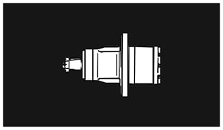
Wheel Motors. Figure 1. Several manufacturers produce hydraulic motors designed especially for wheel drive of a vehicle. Since these motors must carry a part of the vehicle weight as side load on the shaft, the mounting flange is located a short distance behind the front face. This not only allows the vehicle weight to be carried more directly over the shaft bearings, but makes a more compact package, with part of the motor being recessed within the wheel hub.
Wheel motors, regardless of their HP rating, are designed with a large cubic inch displacement per revolution. This gives them high torque output, and matches their speed to vehicle speed, eliminating gear box reducers.
Because of their direct coupling to the wheel, a separate motor must be used on each wheel which is to be powered. Several wheels cannot be driven from the same wheel motor.

Figure 1. Low speed, high torque wheel motor.
Standard Motors. While any hydraulic motor can be used for wheel drive, the speed of standard motors is far too high and their torque is far too low for direct drive to the wheels. They must be coupled either through a gear box speed reducer, or through a reduction roller chain drive. However, one motor can drive several wheels which are mechanically coupled together.
Road Traction
Maximum vehicle traction is obtained just before the drive wheel(s) start to spin. When a drive wheel starts to spin, its traction is reduced, sometimes to almost zero. For optimum vehicle performance, the hydraulic wheel drive motors should be capable of producing sufficient torque, under the most adverse operating condition, to reach wheel spin condition. But torque beyond this level is of no value.
Traction defines the grip between a powered (or braked) wheel and the road surface, and is usually expressed as the amount of horizontal force (drawbar pull), in pounds, that can be exerted against the road surface without slip. Traction depends not alone on the motor torque, but also on the materials in the wheel and road surface, and is directly proportional to the force (vehicle weight) forcing them into contact. Therefore, in vehicular design it is important to consider the number of wheels which must be powered, and the distribution of weight over each wheel.
For simple vehicles running on the Ievel, it may be sufficient to apply drive power to only one wheel. If possible, this should be the wheel carrying the most weight. On more sophisticated applications, involving uphill grades, rapid acceleration, or on vehicles pulling a trailer, it may be necessary to apply drive power to two or more wheels to obtain sufficient traction. An advantage of powering several wheels is that the vehicle is less likely to become stalled by slick spots on the road surface.

Figure 2. Traction is maximum just before wheel spin.
Multiple Powered Wheels. Additional wheels can be powered by using a separate hydraulic wheel motor on each wheel with all of them receiving fluid from a common pump. Wheels or groups of wheels can be mechanically coupled and driven by a common pump. In this case, standard motors instead of wheel motors must be used. Roller chain is often a convenient way of coupling two or more wheels on the same side of the vehicle if the speed is within the safe range of roller chain. If wheel separation is so great that the chain may sag excessively under its own weight, it may be enclosed in guides or supports.
When linking wheels on opposite sides of a vehicle, a solid axle is preferred, if practical. A standard rather than a wheel motor must be used, and it can be coupled through a chain drive on the axle.
If a split axle with differential must be used (for turning corners), a standard motor can be coupled to the input shaft of the differential box. However, split axles should not be used unless necessary, because the vehicle becomes more sensitive to load distribution. With uneven load distribution the total traction will be substantially less than if a solid axle were used.
How to Calculate Road Traction
Traction is the adhesive friction of a wheel against the surface on which it is rolling. The total traction of a vehicle may or may not be the sum of tractions developed by each individual wheel, as noted in the following paragraphs.
Traction of each wheel can be calculated by finding the portion of load weight carried over that wheel, then multiplying times the coefficient of road traction.
In the U.S. system units, traction expressed in pounds exerted in a horizontal direction, and must always exceed the calculated drawbar pull which is required to meet all of the operating conditions for road surface, grade, acceleration, etc. If it is not, the wheels will start to spin prematurely, before performance specifications are met.
Differential Drive. If two powered wheels are operating a differential, total traction will be that calculated for the wheel carrying the least weight multiplied times two.
Solid Axle Drive. If two wheels are connected with a solid axle, traction is computed separately for each wheel and added together to find total traction.
Dual Wheels. Two wheels, side-by-side on the same axle give approximately the same traction as one wheel carrying the same weight. But since two wheels can carry twice the weight of one wheel, they will produce twice the traction when carrying twice the weight. The main purpose of dual wheels is not to get more traction, but to carry more load.
Coefficients of Road Traction
Coefficients of road traction given in the following table are the same as the coefficients of static friction commonly used in other engineering calculations. They are, of course, only approximate and apply to hard, dry surfaces. For other types of wheels and road surfaces, use the coefficient of static friction for these materials published in engineering handbooks. Wheels with lugs are a special case where the coefficient of traction has little to do with the grip of the wheels on the road. The coefficient for lugged wheels could be almost anything, depending on the design of the lugs and the penetration of the road surface.
| Rubber tire on hard surface road | 0.6 to 0.8 |
| Steel-on-steel (railroad or mine engine) | 0.1 to 0.3 |
| Track drive, smooth, without lugs | 0.9 |
| Track drive, with lugs, estimated | 1.4 |
Maximum Traction
Figure 3. It should be noted that the maximum traction of any vehicle regardless of the number of wheels which are powered, is totally dependent on vehicle weight.
Example: A vehicle weighing 5,000 lbs., fully loaded, and having a coefficient of road traction of 0.8, could never develop more than 5,000 × 0.8 = 4,000 lbs. traction (drawbar pull) regardless of how many wheels were powered, nor how high its engine HP. The only way to get more traction would be to increase its weight. The advantage to powering several wheels is to take advantage of vehicle and load weight to get more traction.
In Figure 3, to get maximum traction, all wheels on a vehicle must be powered, and they must all be mechanically linked so the one which is most lightly loaded cannot slip.

Figure 3. For maximum traction, ALL wheels on a railroad or mine engine must be powered.
Rolling Resistance
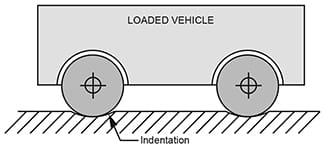
Figure 4. Cast iron or steel wheels running on steel rails is a special case of road surface resistance. As the wheels roll, they slightly indent the rail surface, and must continually climb out of this indentation. A force, called the rolling resistance, and expressed in pounds, must be continually applied as the wheels roll. The amount of this force depends on the materials in contact, the weight over the wheels, and the wheel radius, in inches.
For iron or steel wheels on steel rails, the rolling resistance is about 0.03 lbs. per pound of vehicle weight, and it is inversely proportional to wheel radius, in inches.

Figure 4. Rolling resistance is largely the result
of indentations in the wheel and in the road surface.
Example: For a 10,000 lb. vehicle with 18-inch wheel radius, the rolling resistance = 10,000 × 0.03 ÷ 18 = 17 lbs. This is only the additional horizontal force required to lift the wheels out of the indentations, and does not include normal road and starting resistance, bearing friction, and other losses.
*Methods of estimating drawbar pull to meet specifications on road surface, grade, wind resistance, acceleration, etc., are covered in “Industrial Fluid Power – Volume 3” published by Womack Machine Supply Co.
© 1990 by Womack Machine Supply Co. This company assumes no liability for errors in data nor in safe and/or satisfactory operation of equipment designed from this information.