Data Sheet 55: Simple Measurements in Hydraulic Systems
Easy ways of making some simple tests on hydraulic systems are briefly described in this issue. Some of these tests have been described in greater detail in previous issues. Please request any of these back issues which you do not have.

Figure 1. Suggested circuit locations for pressure gauging stations.
Pressure Gauging Locations
All hydraulic fluid power systems may at some time require troubleshooting, and the most important first step in troubleshooting is to take pressure measurements in various parts of the circuit. When constructing the system, a little forethought in providing gauge points will save a lot of time and trouble if troubleshooting should be required.
Figure 1 shows gauging points which will prove most useful. These are marked with the standard TS symbol (test station). They need be no more elaborate than a tee in the plumbing, with the side port plugged. They cost very little to add to a system.
When using these gauge ports, be sure to clean off the plug before removing it to install a gauge. An air hose, if handy, will do an adequate cleaning job in most cases.
The gauge ports can be a little more elaborate by permanently installing a needle valve in the port, thus permitting the installation of a gauge without shutting down the system. Another arrangement is to install one-half of a quick disconnect coupling in each gauge port, with the mating half of the coupling installed on a gauge. Normally, a pressure gauge should not be left permanently in the system because pressure surges and machine vibration will wear it out prematurely and it will not be ready when needed.
There are plug-in fittings marketed under the name “Reddy-Chek” which allow instant plugging of a gauge into a test station without the use of tools or a shut-off valve.
Checking Pump GPM
Observing the length of time which a cylinder takes to complete its stroke will allow calculation of the GPM oil flow to the cylinder. The pump GPM rating, its RPM, and the bore and stroke of the cylinder must be known.
Use a stop watch or the second hand on a wrist watch to find the number of seconds to make the extension stroke. Calculate the actual GPM flowing into the cylinder:
GPM = [A × S × 60] ÷ [t × 231]
A = piston area, sq. ins;
S = stroke, inches;
t = time, seconds
Compare the calculated GPM with the rated pump GPM. If it is substantially less, part of the pump oil is being lost without producing movement of the cylinder piston:
- Pump may be so badly worn that the internal slippage is quite high. If so, the pump should be replaced.
- Oil in the system is running too hot. The oil has become very thin and slips excessively in the pump.
- Pump may be cavitating and cannot pull in its full displacement. Check the usual causes, dirty strainer, etc.
- Pump relief valve may be set too low, causing a part of the oil to discharge to tank when system builds up high pressure. Be cautious about raising the relief setting. It may cause an overload on the electric motor, or may cause damage to components from overpressure.
- Seals in the cylinder may be so badly worn that they should be replaced.
Measurement of Pressure Peaks
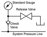
For accurate measurement of peak transient pressures an oscilloscope is needed. However, an approximate measurement can be obtained with a soft seal, leaktight check valve in series with a pressure gauge. For more details of this measurement, please refer to Design Data Sheet 14.

Fuse Tester
Two low wattage (40 or 60 watt), identical light bulbs when connected in series make a simple tester for identifying blown fuses or circuit breakers, and for a rough test of voltage. Solder test leads to the base of the bulbs and wrap well with insulating tape. Two 115-volt bulbs, in series, will light to full brilliance on 230 volts, and glow on 115 volts.
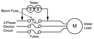
Testing a Loaded Circuit. Figure 2. If the circuit is connected to a load, for example a 3-phase electric motor, test on both sides of each fuse. If bulbs light up, the fuse is open.

Figure 2.
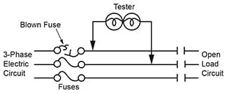
Testing a Non-Working Circuit. Figure 3. If circuit is not connected to a load, test across each pair of wires on the load side of the fuses. If there is one blown fuse, the bulbs will light up when connected across the two good fuses, and will fail to light on the other two pairs of wires.

Figure 3.
Measuring Electric Motor Current
A loop ammeter should be in the inventory of test equipment of every company using integral HP electric motors. Current in each line can be quickly measured without breaking into the wiring. The iron ring on the ammeter is simply looped around each line wire in turn, and the current reads directly on the meter scale.
When attempting to replace an electric motor with a hydraulic motor, any momentary HP overloads during the cycle must be detected, and this can be done with a loop ammeter by monitoring motor current through a complete cycle. Although an electric motor can “ride through” short overloads, a hydraulic motor will stall unless supplied with sufficient pressure to develop enough torque to handle them.
The HP at which an electric motor is operating can be determined by taking line current readings and comparing them with the current stamped on the motor nameplate. If more or less than nameplate rating, the chart on Design Data Sheet 49 will show the operating HP level.
Measuring Oil Temperature
To measure temperature of the oil in a hydraulic reservoir, an ordinary candy thermometer can be inserted through the filler opening after removing the protective screen, if any. Or through any other access hole which may be available. To prevent entry of dirt, the access hole should not be left open any longer than necessary.
Hydraulic Oil Contamination
A complete test of oil condition can only be done in a laboratory with precision equipment, but a few preliminary tests can be made by the user to decide whether more extensive tests should be made. There are several types of contamination which can be harmful to hydraulic components such as pumps, cylinders, and hydraulic motors:
Dirt. Solid particle contamination may enter through the air breather on the reservoir or through the rod seals on cylinders. Or it may be generated within the system, primarily by the pump. If a particle count shows more contamination than the pump can tolerate, additional filtration should be added in the pressure line or return line.
Air. Air may enter through worn shaft seals on pumps, cylinders, and hydraulic motors, from leaks in the pump suction line, low reservoir oil level, etc. While the system is operating, the air mixes with the oil causing it to appear cloudy. Usually the oil clears a short time after the pump is stopped. Air causes excessive wear in the pump, and its point of entry should be discovered and closed.
Water. Water may condense in the reservoir as a result of temperature changes in the air inside the reservoir, or may enter through a leak in a water cooled heat exchanger. Rust formed in the system can be very destructive.
Entrained water mixes with the oil when the system is running, causing the oil to become cloudy. It will usually settle in the reservoir and low places in the plumbing a short time after the pump is stopped. Its presence may be detected by drawing a fluid sample from the reservoir drain valve and allowing it to settle. To eliminate condensed water, a small amount of fluid should be tapped from the bottom of the reservoir daily, as done in a compressed air system.
Chemicals. Oil reacts chemically with oxygen from the air to form undesirable chemical compounds in the oil which cannot be filtered out. These unwanted compounds eventually form the “sludges” found in strainers and on the bottom of the reservoir, and the “varnish” which deposits on valve spools causing them to stick, and which close up small orifices. Oxidation of the oil causes it to darken in color as compared to a new sample of the same oil. If temperature is held below 150°F, with a heat exchanger if necessary, there will be few problems with chemical contamination. But on systems running overheated, these compounds form rapidly, causing many breakdowns and service problems.
Oil Testing. Draw an oil sample while the system is running and allow it to stand several hours. Any change in the oil after standing, oil clears, dirt or water settle out, etc. is an indication that the oil is unfit for use in a modern hydraulic system and should be replaced after corrective measures have been taken, filters installed, water leaks stopped, heat exchanger added, etc. Extremely dark coloration compared to new oil shows that undesirable oxidation has taken place. A sample may be sent to the lab of a major oil company for particle and chemical analysis. However, the sample must be drawn under the “surgically clean” procedure described in ANSI Standard B93.19-1972. This analysis may take from 1 to 4 weeks.
© 1990 by Womack Machine Supply Co. This company assumes no liability for errors in data nor in safe and/or satisfactory operation of equipment designed from this information.