Data Sheet 69: Piston-Type Pressure Intensifiers
Pressure intensifiers are devices which can deliver a small flow of oil (or air) at an unusually high pressure. They offer an economical means of producing high pressure for applications where very little flow is required. The most popular type of intensifier – the piston type – will be covered in this issue, with other types to be covered later.

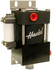
A piston-type intensifier, as pictured here, consists of a large diameter air piston yoked to and driving a small diameter hydraulic piston. The hydraulic pressure which can be pumped by the small piston is directly related to the ratio of areas between the two pistons and the air pressure applied to the input side (air piston). For example, if the large air piston has an area 30 times as large as the small hydraulic piston, and if 100 PSI air pressure is applied to it a hydraulic pressure of 100 x 30 = 3,000 PSI can be produced.
In addition to models which use air pressure on the inlet to produce an intensified hydraulic pressure, models are available for producing intensified gas pressure from compressed air drive.
Intensifiers of the type pictured here have a built-in air valve which causes the air piston to automatically reciprocate when the air is turned on.
An intensifier cannot amplify power. It is a constant horsepower device delivering the same power on the hydraulic output as the air power applied to the input (minus internal friction losses). Input air power to the intensifier is at low pressure with high flow. Output power is delivered at a different ratio high pressure at low flow. An intensifier in a fluid system is comparable to a transformer in an electrical system which receives input power at low voltage, high current and delivers an output at the same horsepower but at a higher voltage and lower current. It is also comparable to a mechanical gear train which receives power at high speed and low torque and delivers the same power at a lower speed with increased torque.
Typical Applications for Pressure Intensifiers
Air-driven pressure intensifiers are not recommended on applications where the hydraulic pressure can be produced satisfactorily with an ordinary gear, vane, or piston pump. As with all compressed air circuits, efficiency of air-driven intensifiers is quite low. They consume a very large volume of air in relation to the hydraulic power produced. The low efficiency is due primarily to the compressible nature of air. Before purchasing one, be sure your plant air supply has sufficient capacity to run it over the time period involved.
The following is a partial list of typical applications which can usually be done better with a pressure intensifier.
1. High Pressure. Very high pressure, impossible with rotary pumps, can be produced up to 15,000 PSI with ease, and up to 200,000 PSI with specially designed models. Intensification level is usually limited by congealing of the fluid at high pressure.
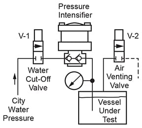
2. Component Testing. Occasional testing or production testing of manufactured parts for physical strength, burst rating, or for leaks – such parts as sand castings or die castings, forgings, welded or seamless pipe, welded containers or assemblies, or pipe lines, to name a few. Leak testing of parts can be done either by holding high hydraulic pressure on the part for a timed interval while watching a pressure gauge to observe any drop in the pressure, or can be done by immersing the part in water while a high air pressure from an intensifier is applied.

In the diagram above, water to prefill the vessel under test can be passed directly through the two check valves which are a part of the intensifier without using additional prefill circuits. To prefill the test vessel, open Valves V-1 and V-2 either with or without the intensifier running. When all air has been expelled from the vessel close V-2 turn on the intensifier, and allow pressure to build to the desired level. A relief valve in the high pressure water circuit is not usually needed because the maximum water pressure will be limited by the air pressure regulator in the air supply to the intensifier.
3. Charging Accumulators. High pressure nitrogen bottles are normally used for pre-charging hydraulic accumulators. However, most of the nitrogen in a pressure bottle becomes unusable when bottle pressure falls below 1,500 PSI. An air-driven pressure intensifier designed for intensifying gas pressure can be used in a cascading circuit to recover most or all of the remaining nitrogen in the bottle. For production work where quantities of accumulators are to be charged, intensifiers may be a money-saving addition to the operation. This application is especially useful in recovering rare and costly gases in certain processes.
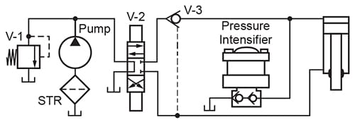
4. Long Holding of Pressure on Presses. An air-driven intensifier, delivering a small volume of hydraulic oil at high pressure is an accurate and inexpensive way of maintaining active pressure under static conditions for an indefinite time without generating heat or consuming power. It will maintain holding pressure on bonding, laminating, or curing presses for long periods while the main pump is turned off.

Holding Active Pressure for a Long Time on a Press
The preceding circuit is the basic circuit used on many types of presses where high pressure must be brought up on the cylinder and maintained in an active state for a long period. The intensifier will maintain an accurate level of high pressure indefinitely, pumping only enough oil to make up for leakage losses in the piston seals and 4-way valve spool. The intensifier consumes little or no power from the compressed air line while it is holding static pressure. During the holding period the hydraulic pump can be unloaded by centering the 4-way valve, or if on an extremely long holding period, the pump can be shut off entirely or used on another press. Valve V-3 is a pilot-operated check valve of the pressure breaker type. It seals high pressure away from the 4-way valve and confines it to the blind end of the cylinder. It also serves to decompress the oil at the start of the return stroke, minimizing hydraulic shock.
5. Gas Storage. Storage of gas in pressure bottles or recovery of an expensive residue gas remaining in such bottles after terminal pressure has dropped below a usable level.
6. Liquid Injection. Air-driven intensifiers may be used for injecting liquids such as odorants, anti·freeze, and lubricants into high pressure gas or liquid lines.
7. Replace Hand Pump. Some installations such as hand-operated shop presses can be upgraded by replacing the hand pump with an air-driven pressure intensifier. Pumping speed can be increased by 5 to 20 times and operator fatigue can be greatly reduced.
8. Fluid Transfer. This is an application where the objective is the pumping of corrosive fluids rather than pressure intensification. Low ratio intensifiers (or even 1:1 ratio models) constructed with stainless steel parts on the outlet side are available to pump fluids which cannot be handled by a conventional rotary pump.
9. Miscellaneous. Numerous small jobs which require only a small movement at high pressure can be done with intensifiers. Some of these applications include squeezing rivets, clamping for spot welding, bending, crimping, forming, piercing, punching, stamping, shearing, marking, etc.
Air Supply for Pressure Intensifiers
On intensifiers driven from a shop air supply there must be a sufficient supply of air available. to keep up with the air demand while the intensifier is running. Full pressure must be maintained on the inlet of the intensifier if maximum pumping rate is to be maintained.
Intensifiers pictured on the opposite side of this sheet have a nominal hydraulic rating of 1½ HP. They require from 5 to 12 HP of compressor HP capacity to keep them in continuous operation (depending on the pumping speed which is acceptable). If intensifier is used intermittently for short periods with a relatively long recovery time between cycles, the average drain on the compressed air system may be considerably less than 5 HP.
Air line filter and regulator units preceding the intensifier should be equal in size to the intensifier inlet port, usually 1/2˝ NPT. For safety the regulator should be a self-relieving type so that if the poppet should develop a slow leak the outlet pressure cannot climb to produce a dangerously high hydraulic pressure when used on a static, long-holding application. Some intensifiers are internally pre-lubricated with a permanent coating of moly-type grease and the manufacturer insists on not adding any lubricating oil to the air supply to avoid washing out the permanent lubricant.
Any valves used in the air supply should be at least equal to the inlet port size to minimize air flow resistance which would reduce pumping speed. Avoid the use of speed control valves in the air supply. If possible, control pumping speed with an air pressure regulator.
Air supply lines from main distribution header into the intensifier should be the same size as the inlet port. Using smaller or unusually long lines will reduce pumping speed.
Exhaust air from the intensifier should be discharged directly to atmosphere if possible, through a large size air muffler. Long or restricted exhaust lines affect the pumping speed even more than small feed lines. If necessary to run a long exhaust line, make it about two pipe sizes larger than the feed line. Too much back pressure in the exhaust line may cause some intensifiers to stall.
Intensified Oil Circuit
All components in the high pressure hydraulic (or air) circuit should have a safety factor of at least 6:1.
Relatively small diameter lines can be used since the flow volume is very small. One exception is lines which also are required to carry a high flow during a pre-fill period.
Seals in all hydraulic components should be leaktight if possible. Leakage rates which may be tolerable in lower pressure systems may be unacceptable in a high pressure system because the volume of slippage represents a higher percentage of the pumped flow. Seals, especially in cylinders which separate two mediums such as air and oil must be especially leaktight to minimize mixing of the two fluids.
At any place in the system where air and oil will be in direct contact at more than 100 PSI without a separating barrier, there will be excessive mixing of the fluids. Oil will vaporize into the air and will be expelled into the atmosphere. This causes untidiness around the machine and is a human health hazard if breathed. Exhaust air should be run through a re-classifier to precipitate the oil.
Use a minimum number of valves in the intensified pressure circuit. Especially avoid spool-type valves at pressures over 3,000 PSI. Leakage across the spool may be intolerable and the spool may stick to the bore if left under full pressure for more than brief periods. Most of the valving should be done in the inlet air circuit if possible.
© 1990 by Womack Machine Supply Co. This company assumes no liability for errors in data nor in safe and/or satisfactory operation of equipment designed from this information.