Data Sheet 23: Minimizing Shock in Hydraulic Systems
Momentary high pressure surges passing through the fluid in a hydraulic system generate noise and may cause hoses to jump and tubing to vibrate. Needless to say, these pressure spikes are a strain on a system and should be eliminated in so far as possible. They cause accelerated wear in pumps and motors by internal bending of shafts and overloading of bearings. A catastrophic failure may eventually occur when a line ruptures or the housing of a component breaks.
Pressure spikes are generated principally during the shifting of valves and during sudden decompression of oil under high pressure. Valve problems will be discussed in this issue: decompression shock will be the subject of a later issue.
Hydraulic Shock From 4-Way Valve Operation

Figure 1. A tandem center spool generates pressure spikes
while spool is traveling between positions.
Figure 1. Tandem center 4-way valves offer a convenient and economical way to control a hydraulic cylinder and to unload the pump when the valve spool is centered. But these valves are apt to generate a pressure spike in the pump line while the spool is moving between positions.
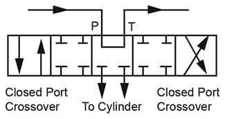
Figure 2. Expanded diagram of tandem center spool.
Closed porting in the crossover positions is standard.
Figure 2. This is an expanded diagram of the standard tandem center spool used in Figure 1. At intermediate points between the end positions and center, the spool travels through crossover positions in which the pump flow is momentarily blocked. A pressure spike is produced because of the momentarily increase in energy level due to the pressure and velocity heads in the pump line.
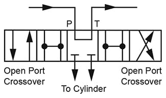
Figure 3. Open porting in the crossover positions reduces
pressure spikes but spool leakage rate is higher.
Figure 3. Tandem center valves are available from most manufacturers which have special spools with open porting in the crossover positions. These do reduce the shifting shock but have more spool leakage because of reduced sealing length on the spool. On manual valves, the load can be dropped if the operator hesitates while shifting the spool.
When designing industrial hydraulic systems using solenoid 4-way valves, we suggest limiting the use of tandem center valves to low power systems, say under 25 HP. On high power systems, closed center valves should be used with the unloading arrangement of Figure 4.

Figure 4. This circuit eliminates spool shifting shock in solenoid valve circuits. Turn page over for description.
Figure 4. Vent-type pump unloading is preferred over tandem center valve unloading on industrial hydraulic systems using solenoid 4-way valves for two good reasons:
- Pressure spikes generated when the valve spool shifts are virtually non-existent. By the time the spool reaches crossover position, high flow and high pressure have already been dumped to tank through the vented relief valve.
- Several branch circuits can be operated from one pump in a parallel circuit with full pressure available to all branches simultaneously. Tandem center valves operating several branch circuits must be connected in series, and full pressure is not available to all branch circuits at the same time.
The relief valve in Figure 4 functions not only as an adjustable maximum pressure limiter but also, when vented, as a pump unloader. It must be a 2-stage valve, also called a pilot-operated relief, and must have an external vent port (sometimes called an RC, remote control port).
All branch circuits should have 4-way valves with blocked pressure port so they can be connected in parallel. Closed center, float center, or 2-position (no center neutral) types may be used. The pump is unloaded by venting the pilot operated relief valve when all branch circuit solenoids are de-energized. When Solenoid C is de-energized, the relief valve loses its pressure holding ability, opens up, and allows the pump oil to flow to tank with very little resistance. When Solenoid C is energized, the vent line is blocked and the relief resumes its normal functioning as a maximum pressure limiter at the pressure set on its adjusting knob.
When designing the electrical control circuit, each time any one of the valve solenoids, A, B, etc. is energized, Solenoid C must also be energized through a separate set of contacts in order to load up the pump to obtain pressure. When all 4-way valves are centered, Solenoid C must also be de-energized, to unload the pump.
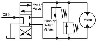
Figure 5. Cushion Relief Valves for Hydraulic Motor
Figure 5. Cushion Relief Valves. Most of us are familiar with cushion valves across the ports of hydraulic motors to decelerate the motor safely to a stop when the spool of the 4-way valve is centered or when it is passing through a closed port crossover position. These valves should be non-adjustable, and have a cracking pressure about 500 PSI higher than the maximum system pressure. They give very abrupt stopping, sometimes too abrupt.
Most hydraulic motors should be protected with cushion valves, the exceptions being low speed operation (below 500 RPM) or when the load is mainly friction or pure torque, rather than rotation of a large mass.
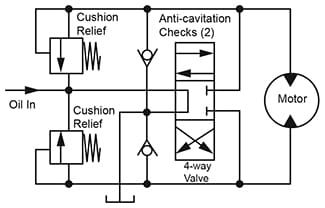
Figure 6. Infinitely Adjustable Motor Cushioning
Figure 6. Adjustable Cushioning. This is a much better cushion circuit where a softer stop is needed. The two cushion relief valves, one for each direction of rotation, may be set for any degree of deceleration from very abrupt to very soft. Instead of discharging to the opposite motor port as in Figure 4, they are connected to the pump pressure line. Pressure in this line blocks them while the motor is running, and though they may be set very low they cannot limit the system pressure. But when the 4-way valve spool is centered, this pump line goes to tank and cushioning becomes effective.
To prevent cavitation of the motor inlet when oil discharges across the cushion relief valves, a pair of check valves is added. These should have low cracking pressure, 3 PSI, and should be plumbed to the tank port of the 4-way valve where they can take advantage of back pressure in the tank return line to help the check valves open.
Relief valves for cushioning should fie poppet-type (not spool-type), direct-acting (not pilot-operated). This type is considered to have the fastest response to pressure spikes.
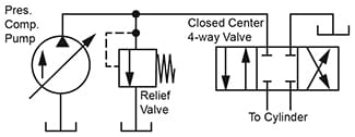
Figure 7. Relief Valve With Pressure Compensated Pump
Figure 7. Pressure Compensated Pumps. Circuits for these pumps ordinarily use a closed center 4-way directional valve. The question is whether a relief valve should be used to absorb pressure spikes generated when the 4-way valve spool is centered and before the compensator has time to act. Each manufacturer will furnish data on compensator response and whether a relief valve should be used. However, even with a very fast acting compensator of 50 milliseconds, if the connecting line between pump and 4-way valve is very short, the enclosed volume of oil may not be sufficient to contain the rise of pressure spikes, and a miniature relief valve is advised. As a general rule, a relief valve is always recommended if the response is slower than 100 milliseconds.
Hose Connections. Valve shifting and decompression shocks can be minimized although not completely eliminated by using hose connections, instead of rigid plumbing between a hydraulic cylinder and its 4-way control valve.
© 1990 by Womack Machine Supply Co. This company assumes no liability for errors in data nor in safe and/or satisfactory operation of equipment designed from this information.