Data Sheet 42: Matching a Hydraulic Motor to the Load
On the design of a new machine which is to be run with a hydraulic motor, a determination of required speed and horsepower must be made so a model with suitable ratings can be selected. This issue describes several methods of making such a determination.
Hydraulic vs. Electric Motor Characteristics
Designers who are experienced only in selecting electric motor drives need to be careful in designing hydraulic drives because of important differences between these two motors.
Normally, an electric motor is selected on the basis of horsepower. It is selected to match an existing power source which provides constant voltage and frequency. If it happens to be a little oversize for the job, no harm is done, although it may cost a little too much.
This is not true of a hydraulic motor. It is selected on the basis of torque and speed rather than horsepower. It cannot be selected without also considering the pressure and flow of the pump which will supply it with fluid. If it is inadvertently selected oversize for the job, its performance will not be as good as if it were correctly sized. Hydraulic pump and motor must work as a team. For optimum performance, the pump and motor must be correctly matched.
An electric motor is relatively easy to select because, at any given horsepower, there are only a few fixed speeds from which to choose, and it does not have to be matched to the alternator which supplies the power. On an induction type electric motor, starting torque is always greater than running torque, so this type motor can start any load which it can run. It can start under a full torque load, or even an overload, although if started too frequently, there will be an excessive heat build-up in the windings.
The reverse is true of a hydraulic motor. Starting torque is uncertain, but nearly always is less than running torque, so this type motor cannot necessarily start under full load but it can run any load it can start. Usually, it cannot start a full torque load unless it has been oversized to gain starting torque. If purposely selected oversize, then it will likely have poor speed regulation with the result that it cannot cover as wide a speed range with acceptable performance.
Torque Determination
Torque, not horsepower, is the basis for proper selection of a hydraulic motor. In nearly every application the desired speed is already known, leaving only the torque to be determined.
Torque is always the most significant factor in any hydraulic motor system – much more significant than either speed or horsepower. Unless the motor has sufficient torque to start the load or to run it at maximum speed, the system can never work properly no matter how much horsepower is available.
After a hydraulic motor has been tentatively selected, the horsepower can be computed from speed and torque. If this turns out to be more than is available from the pump, then some of the speed must be sacrificed, but never the torque
Load torque is the twisting or turning effort which must be exerted on the load shaft to start the load and/or to run it at maximum rated speed. This torque must be supplied by the hydraulic drive motor. The amount of torque which will be required from the motor can be estimated in one of several ways:
Torque Estimation by Measurement
It is essential that characteristics of the load be considered when attempting to estimate hydraulic motor torque for starting and/or running. Some loads require more torque to break them away from a standstill than to run them after they have started. Other loads require only a small amount of breakaway torque but torque requirements increase in proportion to speed.
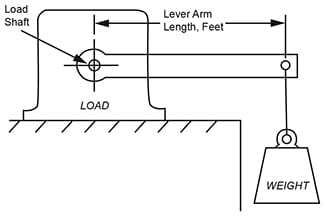
Breakaway Torque. Figure 1. Breakaway, or starting torque can be measured with a torque wrench on small machines, or by using a long lever loaded with weights until the load shaft breaks away and starts to rotate. Torque is calculated by multiplying lever arm length, in feet, times the weight necessary to break the shaft away. Torque will be in foot-lbs. On this type load, if the hydraulic motor can supply breakaway torque, it can also run the load at any speed.

Figure 1. Breakaway torque of a load can be measured
with a lever and weight, a spring scale, or a torque wrench.
Electric Motor Substitution. The running torque can be determined by temporarily coupling an electric motor to the load shaft and measuring the motor line current while it is running. By referring to a torque/current performance curve for the motor, the running torque can be determined with a fair degree of accuracy. Then, a hydraulic motor can be selected and the system PSI can be established which will give the required running torque. Of course the electric motor speed should approximate the maximum running speed of the load.
Torque Estimation by Comparison
This is the easiest method where applicable. The proposed new machine can be compared with an existing machine which does essentially the same job, and on which the torque and speed, or horsepower, are known.
But perhaps the new machine is to produce twice as many parts per hour as the existing machine. Then basically the new machine will require twice the horsepower. Perhaps the new machine will manufacture parts of the same size but twice as fast; hence twice the horsepower. Or perhaps larger parts are to be manufactured which will require twice the torque but at the same production rate. Again, twice the horsepower will be required. Suppose the new machine is to manufacture the larger parts and at twice the rate of the existing machine. Then four times the HP is needed.
Estimation is by comparing horsepower; then the HP can be divided by speed to find the hydraulic motor torque.
Caution! If the existing machine is powered with an electric motor and the new machine with a hydraulic motor, and if high starting torque is required, the hydraulic motor must be selected by comparing its starting torque with the starting torque of the electric motor on the existing machine. An induction type electric motor can produce about 3 times the starting torque of most hydraulic motors of the same horsepower rating.
Torque Estimation by Calculation
On machines of new design- where there is no way to measure input torque, nor to compare performance with an existing machine, torque and HP must be calculated.
Since the final output of the machine will be mechanical, the starting point for calculations is to compute the mechanical output HP.
If the machine output will be linear motion, use this formula to compute HP output:
HP = (F × D) ÷ [t × 33,000], in which:
F is the linear force output, in lbs.;
D is distance, in feet, through which the force is exerted;
t is time, in minutes, that the machine exerts force, F, through distance, D.
If the machine output will be rotary, use this formula to compute the mechanical HP output;
HP = T × RPM ÷ 5,252, in which:
T is the torque produced, in ft. lbs.;
RPM is the speed of the rotary output.

Torque must be calculated on most new designs.
No calculations are possible unless the force, and travel distance during a specified time interval are known or assumed.
After HP output is determined, work backwards toward the input shaft of the machine, one step at a time, adding sufficient HP at each step to make up for friction losses in gear boxes, bearings, etc. This will give the estimated HP required from a hydraulic motor coupled to the input shaft.
In a similar manner start with the output speed and work back toward the input, adjusting for speed changes through chain drives, gear boxes, etc., finally arriving at the speed of the input shaft to which the hydraulic motor will be coupled.
From these estimations of input HP and speed, the hydraulic motor torque can be computed:
T (torque in ft-lbs) = HP × 5252 ÷ RPM
Winch Example: A winch, having a 20″ diameter drum, must raise a 15,000 load at a speed of 3 ft/second. Mechanical HP is calculated as follows:
HP = (15,000 × 180] + [1 × 33,000] = 81.8 HP
15,000 lbs. is force to move load; 180 ft. is distance traveled in one minute (computed from 3 ft/sec); 1 represents a time of 1 minute.
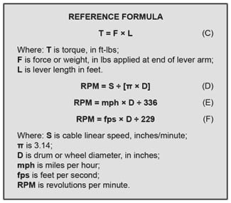
Drum RPM is computed from Formula (D) in box; input speed for the hydraulic motor is computed as described above in this column.
Drilling Machine. On a machine for drilling, the drill manufacturer will usually furnish HP and recommended speed specifications. These figures can be adjusted back to the input shaft of the drilling machine, making allowances for frictional losses and speed changes.
Vehicle Wheel Motor. Calculate the total drawbar pull (horizontal thrust) to overcome all road and operating conditions. Using the wheel radius, calculate wheel torque with Formula (C) in the box below. Convert travel speed into wheel RPM. Select hydraulic wheel motor to meet these conditions. Information for estimating drawbar pull and making calculations is given in “Industrial Fluid Power – Volume 3” published by Womack Machine Supply Co.

© 1990 by Womack Machine Supply Co. This company assumes no liability for errors in data nor in safe and/or satisfactory operation of equipment designed from this information.