Data Sheet 40: How to Control Air Motors
Background Information. The fluid power user should not overlook the advantages of air motors on certain applications where they may perform better than either electric motors or hydraulic motors. They will work in hostile environments such as extreme heat or cold, in corrosive, flammable, or explosive atmospheres. They can be controlled with simple valving, can be instantly reversed, stalled indefinitely without damage, and can be mounted to run in any position.
Small vane-type and piston-type motors are available up to 3 HP. Larger piston motors are available up to 25 HP. While most of them are best suited for high speed, low torque applications, at least one new design has been introduced for low speed, high torque operation.
They do have certain limitations. They are less efficient than other motors. They have poor speed regulation; that is, they change their speed according to the load. If the load should change, their speed also changes.
Directional Control of Single-Rotation Motors
Figure 1. The simplest start-stop control is any kind of 2-way valve – ball, gate, globe, plug, spool, placed in the air supply to the motor inlet.
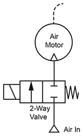
Figure 1. Start-Stop.
Figure 2. If the motor must be relieved of an air block on both ports while stopped, a 3-way valve may be connected as in this figure.
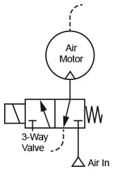
Figure 2. Vented Stop.
Figure 3. For a more rapid stop after the air has been shut off, a 4-way valve, check valve, and needle valve may be connected as shown. During normal running (solenoid energized), most of the exhaust air from the motor will go to atmosphere relatively unrestricted through the check valve and 4-way valve. While stopping (solenoid de-energized), exhaust air being no longer able to go through the check valve, is forced through the needle valve and can be restricted as much as desired.
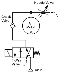
Figure 3. Cushioned Stop.
Directional Control of Reversible Motors
Directional control of air motors is different from that of air cylinders. Cylinders are allowed to stall against a positive stop, under pressure, at each end of their stroke. With air motors, pressure should be removed from both ports while they are stopped to avoid the excessive waste of air due to their internal leakage. This calls for a 3-position 4-way valve in which air pressure is blocked in neutral, either a closed center (Figure 4) or a float center (Figure 5), according to the needs of the application.
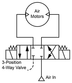
Figure 4. Closed Center Valve.
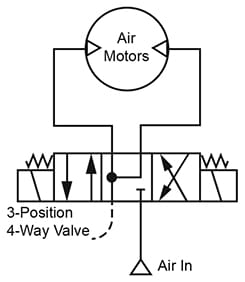
Figure 5. Float Center Valve.
Torque and Speed Control of Air Motors
Torque of an air motor is directly proportional to the difference in pressure between inlet and outlet ports.
Running Torque. Output torque on the shaft reaches a maximum just after the motor starts, then drops off sharply as speed increases until it becomes zero when the motor reaches its free running speed. At this speed there is no torque output because all the torque is consumed internally in overcoming friction and air flow losses.
When the motor is coupled to a load, it rotates the load as fast as it can according to the torque required by the load. If the load should decrease, the motor increases its speed until its torque again matches the load requirement. If the load should increase, the motor slows down until there is again a match between its torque output and the load requirement. In this respect an air motor acts very much like an air cylinder; its speed increases or decreases as the load respectively decreases or increases.
Stall Torque. While the motor is running, if the shaft load should be gradually increased, the motor will continue to decrease its speed until the point of maximum torque is reached, at perhaps 25 to 100 RPM. Since this is the highest torque which it can produce, any further increase in torque load will cause it to suddenly stall.
Starting Torque. Starting torque of an air motor is quite low, less than 75% of its maximum running torque. Starting torque can be increased by proper circuit design and adjustment, by exposing the motor, at the moment of starting, to a higher pressure than its normal running pressure.
Increasing the Starting Torque. Figure 6. Most air motor applications will need a speed control valve to set the speed while the motor is running under load. The key to improve starting torque is to place the speed control in the motor outlet, or in a meter-out mode on reversible air motors.
Pressure gauge readings in Figure 6 are shown just after air pressure is applied but before the motor starts. Since there is yet no air flow, there will be no pressure drop across the speed control valve, and full line pressure will appear across the motor ports. Starting torque is, therefore, a function of the full line pressure.
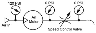
Figure 6. Pressure relations at the moment of starting (no air flow).
Figure 7. As the motor comes up to full speed, pressure across the motor will decrease to its normal running value as pressure drop appears across the speed control valve due to air flow. Running torque is, then, a function of line pressure minus pressure drop-across the speed control valve.
To get full benefit from this method of increasing the starting torque, the control valve which admits air to start flow to the motor should be a fast-opening type, like a solenoid valve, and not a valve which could be gradually opened by an operator.
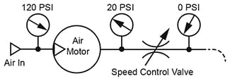
Figure 7. Pressure relations when motor reaches full speed (full air flow).
Torque and Speed Control of Reversible Motors
Figure 8. A complete control circuit for a reversible air motor would include a pressure regulator upstream of the 4-way valve. This controls maximum starting, running, and stall torque, and prevents excessive pressure from reaching the motor.
Most small air motors are designed to operate at no more than 100 PSI differential pressure across their ports. For example, if the regulator were set for 120 PSI, this would allow 20 PSI pressure drop across the flow control valves and still give full operating pressure across the motor. Starting torque would be developed at 120 PSI, running torque at 100 PSI.
The circuit should include a pair of flow control valves in the motor lines connected as meter-out speed controls.
Rather than the closed center 4-way valve, a float center valve might give more starting torque by preventing pressure from being trapped between valve and motor when the motor was stopped.
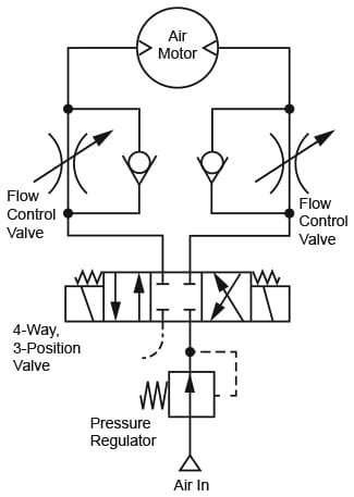
Figure 8. Torque and speed control of a reversible air motor.
© 1990 by Womack Machine Supply Co. This company assumes no liability for errors in data nor in safe and/or satisfactory operation of equipment designed from this information.